Let’s look at a simple model of GPR signal reflection/propagation which takes into accounts only the distance between the GPR antenna and the target. We will not take into account signal attenuation, reflection from the interface between air and surface and many other factors – this model is to demonstrate the influence of distance only.
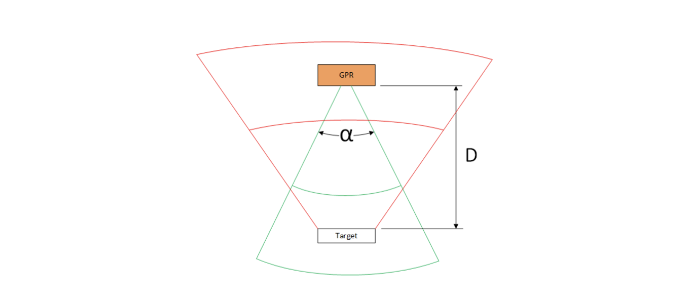
We will assume that GPR emits impulse in the form of a cone – it is a rough assumption, but, again, should be OK for our mental experiment (see Fig.1 - GPR emitting impulses in the form of a cone).
GPR emits an impulse with energy E (the green cone in the picture above). Area of the flat horizontal part of the target is S, distance between GPR antenna and target is D.
When cone’s angle is α, the amount of GPR impulse’s energy that will hit the target (Et) may be estimated using the formula:
The only important thing here is that the amount of energy received by the target decreases as the second power of the distance between the antenna and target.
Next, the target will reflect a part of the received Et energy back. For simplicity, we will assume that the target will reflect almost 100% of energy (it can be a steel plate in dry sand). As the probability that our target will act as a focused reflector with direction back to GPR antenna is very low, the reflected impulse will form some cone (in red in the picture).
The receiving GPR antenna will get a fraction of the energy of the reflected signal, and it will be also decreased as the second power of the distance D. Let’s call the received amount of energy Er (energy received).
What will happen if the distance will be increased two times?
Et – will decrease 4 times (the second power of the distance increase!).
Er – will decrease 4 x 4 = 16 times compared with the initial values!
So, in ideal conditions, when we increase the distance between the GPR antenna and the target, the amount of energy received from the target will drop as the 4th power of the distance. In a real-world situation, this will be even worse as the resolution (in the horizontal plane) of the GPR also depends on distance, a more elevated antenna will receive more air reflections, etc.
What does this all mean for the GPR on drones? You should fly as low as possible as the probability to detect even shallow subsurface targets will decrease as 4th power of the antenna altitude.
Non-technical limitation
In many countries, there is a set maximum altitude of 1m for GPR antennas over the surface.
These countries are the US, Canada, the UK, most of the EU countries, and some others.Because of that, the use of GPR systems on drones that can't follow terrain with an altitude of 1m - might be against the law.
When cone’s angle is α, the amount of GPR impulse’s energy that will hit the target (Et) may be estimated using the formula:
Distance matters also for magnetometers
Magnetometers are passive devices; they measure the magnetic field at the point where the sensor is. They don’t have such a characteristic as “range”. The principle of detection of something (artificial objects, utilities, UXO, mineral deposits, etc.) is based on the analysis of magnetic field differences. If in some spot or area the magnetic field differs from the surroundings, that means that “something” can be there.
This spot where the magnetic field differs is called an “anomaly”. Unfortunately, the amplitude of magnetic anomaly produced by concentrated masses of ferrous/magnetic substances decreases as the 3rd power of the distance from the object.
We may illustrate this using an example of UXO detection. Hand grenade F1 at the depth of 30cm under surface is detected as a magnetic anomaly with an amplitude around 3.5 nT (nanotesla) using SENSYS MagDrone R4 magnetometer from the altitude of 0.5m. From the altitude of 1m, this target produces an anomaly with an amplitude < 0.5 nT and becomes practically invisible in real-life conditions.

Image of hand grenade and visualization of its magnetic anomaly detected from 0.5m AGL.